



How to Read Architectural Drawings: A Beginner's Guide for Homeowners
A plain-English guide to floor plans, elevations, sections and scale, so you can read your architect's drawings and ask better questions with confidence.
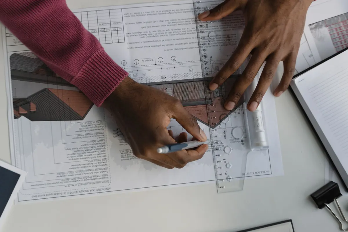
A rolled set of architectural drawings can feel like a foreign language delivered in a cardboard tube. Give it twenty minutes, though, and the machinery underneath becomes visible. A plan is a slice, an elevation is a face, a section is a cut. The conventions repeat from sheet to sheet, and once you can follow them you can read your own project instead of waiting for someone to translate it.
Start with the title block
Every sheet carries a title block, usually bottom right or running up one edge. It gives the project name and address, the drawing title, its number, the scale, the revision letter, the date and the status. That last one matters more than most homeowners expect. A drawing marked "For Planning" is a statement of intent; one marked "For Construction" or "As Built" is what the builder will actually work from.
Drawing numbers are coded by discipline: architectural sheets often begin with A, structural with S, electrical with E. When you see A-102 Rev C, that sheet has been changed at least three times. Revision clouds and small numbered triangles in the margin mark what changed. Keep the drawing register that comes with the set and check your printed copy against it, because working from a superseded sheet is one of the most common and expensive mistakes on a home project.
It helps to write the current revision letter in pencil on the corner of every printed sheet as soon as you receive it. Ten seconds of work, and it stops a builder working from an old page that has been sitting in a van since March.
Floor plans: the view from above
A floor plan is an imaginary horizontal cut through the building, roughly a metre above floor level. Everything above the cut is removed and you look down on what remains. That single idea explains almost everything about them.
Walls appear as two parallel lines, filled or hatched. Doors show as an opening with a quarter-circle arc: the straight line is the door leaf, the arc shows the swing, and the corner where they meet is the hinge. Windows sit inside the wall as thinner lines. Stairs appear as a run of treads with an arrow and the word "up" or "down". Line weight carries meaning:
- Thick solid lines — walls cut through by the imaginary slice, typically external and load-bearing walls.
- Thinner solid lines — internal partitions, joinery, sanitaryware, kitchen units.
- Dashed lines — elements above the cut, such as a beam or wall unit, or hidden below it, such as drainage.
- Hatching or solid fill — a particular material, often masonry or existing structure.
Find the north arrow. It rarely matters for a kitchen layout, but it matters enormously for daylight, solar gain and where to put a garden room. Ground floor, first floor and roof plans follow the same logic at different heights. What plans cannot show you is height. A doorway looks identical whether the ceiling above it sits at 2.1 m or 2.7 m; for that you need a section.
One practical trick: trace the route you take every morning, from bed to bathroom to kettle, on the plan with your finger. Awkward pinch points, doors that open into each other and a kitchen island that leaves a 600 mm gap all show up instantly, long before anything is built.
Elevations: the flat face of the building
An elevation is a straight-on view of one side of the building, drawn without perspective. It is named either by purpose (front, rear) or by compass direction (north, south). Because there is no vanishing point, depth disappears: a bay window two metres deep looks barely different from one 300 mm deep. Read elevations for height, alignment and appearance rather than for depth.
They show the roofline and pitch, window heads and sills, door positions, chimneys, gutters and downpipes. Existing and proposed ground levels are usually marked, which is how you spot that a new patio will sit a step below the kitchen door. Material notes appear as labels with leaders pointing to the relevant surface.
Exterior elevations are also where proportion lives. If a window looks mean or a roof looks top-heavy on the drawing, it will look that way in brick, and it is far easier to redraw a window than to rebuild one.
Sections: the building sliced open
A section is a vertical cut through the building, drawn as though you had sawn through it and looked sideways at the exposed edge. It answers the questions a plan cannot: how high, how thick, how does it all stack together.
A good section will show floor-to-ceiling heights, the build-up of floors and roof, insulation, foundation depth, roof pitch, eaves and ridge details, and the rise and going of the stairs. If you are worried about headroom on a landing, the section is where you measure it. If a new beam looks as though it might clip the top of the stairwell, the section settles the argument before the steel is ordered.
Plans tell you where things are. Sections tell you whether you can stand up in them. When the two disagree, the section usually wins.
Scale, dimensions and why you should never measure off the drawing
Scale is the ratio between the drawing and the real thing. In metric, 1:100 means one centimetre on paper equals one metre on site; 1:50 is twice as detailed, and 1:20 or 1:5 is used for junctions, stair details and window heads. A scale bar sits next to the title block so the drawing can be checked, not just trusted.
Here is the trap. Most office printers and home printers quietly "fit to page", shrinking the sheet by a few per cent. A 1:100 plan printed at 96 per cent is no longer 1:100, and a kitchen measured from it will be wrong by 40 mm per metre. Always print at 100 per cent, and always trust the written dimensions over anything you measure with a ruler.
Dimension lines run between thin extension lines and end in small ticks or arrows, with the figure written above the line. Learn the difference between running dimensions (measured from one fixed point, so errors do not accumulate) and chain dimensions (each measured from the last). If two figures on the same plan add up to something different from the overall dimension, do not guess — ask.
Symbols, abbreviations and schedules
Drawings lean heavily on shorthand. Doors and windows are tagged with codes such as D1, D3 or W2, and those codes refer to a schedule, usually printed on the same sheet or the next one, listing size, type, material, glazing and fire rating. Finishes are tagged the same way: a floor might read "F2 — engineered oak".
Watch for the legend, which explains any hatching or symbol used on that sheet, and the key plan, which shows in miniature which part of the building the current sheet covers. Abbreviations are worth a quick look too; "FFL" means finished floor level, "GL" ground level, "TBC" — worryingly common — means to be confirmed.
Cross-checking: how the sheets talk to each other
No sheet stands alone. Move a wall on the ground floor plan and it should move on the elevation and the section. Add a roof light and it should appear in the roof plan, the elevation and the section. Reading a set properly means flipping back and forth and asking whether the same building is being described twice.
Pay particular attention to anything marked "TBC", "by others" or "refer to engineer". These are the gaps where cost and delay live. A schedule that names a window size the plan does not match is not a detail; it is a problem that will surface on site, at the least convenient moment.
Questions to ask before you sign anything off
You do not need to understand every line to ask good questions. A short list, asked early, saves a great deal of grief:
- Which revision am I looking at, and is this the latest?
- What is still marked TBC, and who is resolving it?
- Do the dimensions on the plan match the schedule and the section?
- Are the ceiling heights written down anywhere, and do they work for me?
- What is the status of this drawing — planning, tender or construction?
None of this makes you a designer. It makes you a client who can follow the conversation, spot the obvious mismatch and ask the question that needs asking. That is usually enough to keep a project on its feet.
Photo: Tima Miroshnichenko / Pexels